Manufacturers are under constant pressure to increase output without sacrificing product quality. UV LED curing offers a practical route when adhesives, coatings, or inks require fast and controlled processing. Unlike traditional mercury lamps, UV LED systems produce focused ultraviolet energy with lower heat transfer to nearby materials. This can protect heat-sensitive plastics, reduce waiting time, and support more consistent production cycles.
But how does uv led curing improve manufacturing efficiency in real operations? The answer depends on process design, material compatibility, and accurate dose control. A well-selected system can deliver instant on-off operation, reducing warm-up delays during short production runs. It may also lower energy consumption and simplify maintenance because LEDs have long service lives. These benefits become visible on the factory floor: fewer pauses, cooler workpieces, and steadier conveyor movement.
The gains are not automatic.
From practical line evaluations, curing performance often changes with distance, wavelength, surface geometry, and adhesive thickness. Operators should verify irradiance with calibrated equipment rather than relying on lamp settings alone. Production teams also need to test shadowed areas and confirm full cure strength through documented inspection methods. A faster cure is not useful if it creates weak bonds or rejected parts. That point is easy to overlook. This guide explores seven realistic ways UV LED curing can improve manufacturing efficiency while acknowledging its limits, setup demands, and the importance of evidence-based process control.
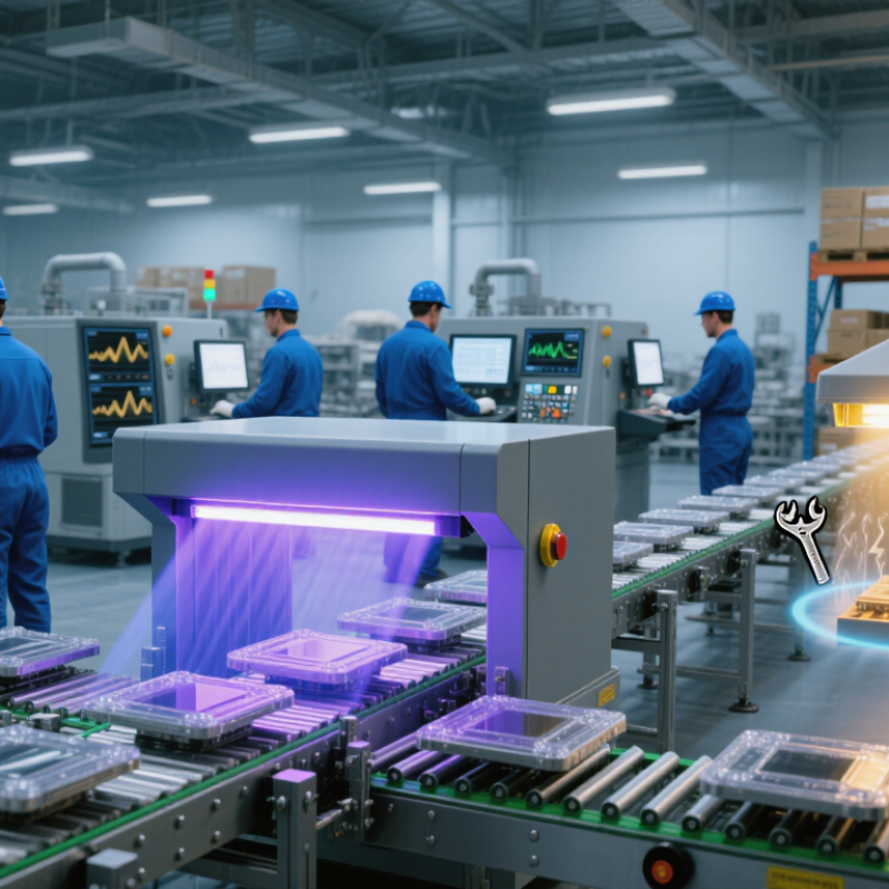
UV LED curing uses semiconductor light sources to trigger photochemical reactions in specially formulated inks, coatings, adhesives, and sealants. Unlike thermal drying, it can cure material within seconds, often at lower process temperatures. That matters when manufacturers handle heat-sensitive plastics, electronics, or thin films.
The process begins with wavelength matching. Confirm that the photoinitiator responds to the selected UV output. Measure irradiance, energy dose, belt speed, and working distance during every validation run. Small changes matter. A 2023 report from the U.S. Department of Energy identifies long operating life and lower maintenance as major benefits of solid-state lighting. LED sources commonly support 25,000 to 50,000 hours, although real curing performance depends on cooling and operating conditions. Keep lenses clean. Check them daily. Monitor temperature around the curing head.
Efficiency also depends on production discipline. Standardize lamp height and exposure time across workstations. Record rejected parts before changing the process. Improve ventilation around the curing area, even when the system produces less heat. Follow the coating supplier’s technical data and verify full cure with adhesion, hardness, and chemical-resistance tests. RadTech’s industry guidance emphasizes dose control, formulation compatibility, and process validation for UV and electron-beam applications. One overlooked issue is shadowing. Complex parts may receive uneven exposure, despite acceptable surface readings. Rotate components, add multiple light angles, or redesign the fixture when necessary. The “best” setting may still waste energy. Reliability grows from repeated measurements, not confident assumptions.
| Tip | Efficiency Action | Key Operating Dimension | Practical Target or Range | Expected Manufacturing Benefit | Recommended KPI |
|---|---|---|---|---|---|
| 1. Select the Correct UV Wavelength | Match the LED wavelength to the photoinitiator absorption profile and the substrate requirements. | Common UV LED wavelengths | 365 nm, 385 nm, 395 nm, or 405 nm, depending on the formulation | Improves cure reliability, reduces under-cured parts, and limits unnecessary exposure time. | First-pass cure acceptance rate (%) |
| 2. Control UV Dose, Not Just Exposure Time | Measure irradiance and exposure time together because UV dose is calculated as irradiance multiplied by time. | UV dose | Dose in mJ/cm²; establish a validated minimum and maximum for each product | Creates more consistent curing across shifts, machines, and production lots. | Dose variation (%) and cure-related defect rate (%) |
| 3. Optimize LED-to-Part Distance | Position the curing head close enough for effective irradiance while maintaining uniform coverage and safe material handling. | Working distance and irradiance uniformity | Use a validated distance; verify irradiance across the full cure area | Reduces shadowing, edge defects, and repeated curing caused by uneven energy distribution. | Minimum-to-maximum irradiance ratio across the work area |
| 4. Use Closed-Loop Process Monitoring | Monitor LED output, temperature, operating time, and alarm conditions with calibrated sensors. | Process control frequency | Check critical parameters at start-up and at defined intervals during production | Detects output drift before it creates a large batch of nonconforming parts. | Unplanned downtime, alarm response time, and rejected units per batch |
| 5. Manage Thermal Conditions | Use appropriate heat sinking, airflow, and temperature monitoring to keep LED output stable. | LED and workpiece temperature | Operate within the curing-system and material supplier’s specified temperature limits | Helps maintain stable irradiance and prevents heat-sensitive substrates from deforming. | Temperature deviation, thermal alarms, and heat-related defects (%) |
| 6. Schedule Preventive Maintenance | Clean optical surfaces, inspect cooling components, verify interlocks, and recalibrate radiometers on a documented schedule. | Maintenance interval | Set intervals according to dust, operating hours, process criticality, and equipment guidance | Preserves optical output, reduces emergency stoppages, and extends equipment service life. | Mean time between failures, maintenance compliance (%), and irradiance loss (%) |
| 7. Integrate Curing With Line Automation | Connect curing controls with conveyors, sensors, inspection systems, and production records. | Line synchronization | Use recipe-based settings, interlocks, and automatic pass/fail verification | Reduces manual handling, prevents skipped cures, and improves traceability. | Units per hour, cycle-time variation, manual touches per unit, and overall equipment effectiveness |
Note: UV dose, wavelength, working distance, temperature limits, and maintenance intervals must be validated for the specific adhesive, coating, ink, substrate, and curing equipment used in production.
It uses UV light to trigger chemical reactions in inks, coatings, adhesives, and sealants. Curing can finish within seconds.
It often works at lower process temperatures than thermal drying. This can protect thin films, plastics, and electronic parts. Heat still matters.
Match the LED wavelength with the photoinitiator’s absorption range. An incorrect match may leave the material soft or weak.
Record irradiance, energy dose, belt speed, working distance, and lamp temperature. Measure dose in mJ/cm², not electrical power alone.
They can, but shorter exposure may reduce curing strength. Test the fastest planned speed with the thickest and darkest material.
Check hardness, adhesion, and chemical resistance. A glossy surface can still hide weak bonding underneath.
Fixtures may create shadowed areas. Rotate the component, add light from another angle, or redesign the fixture.
Clean the lenses daily and monitor temperature around the curing head. Check output periodically because light intensity can drift.
Not automatically. Savings depend on dose, exposure time, cooling, process speed, and rejected parts. The expected result may be imperfect.
Do not solve every curing problem by increasing power. I once created brittle edges that way. Measure the cause first.
UV LED curing can help manufacturers increase throughput by curing coatings, inks, and adhesives quickly and consistently while using energy more efficiently than many conventional curing methods. Before adopting the process, assess the materials, product dimensions, line speed, and quality requirements to determine whether UV LED technology fits the production task. These needs guide equipment selection and help establish practical performance goals.
To improve results, tune exposure time, light intensity, and positioning for each application, then verify that curing is complete and repeatable. A well-matched system can reduce heat-related issues, energy consumption, and maintenance needs. Track cycle times, reject rates, energy use, and equipment downtime to see how does uv led curing improve manufacturing efficiency in practice. Regularly reviewing these measures helps identify workflow bottlenecks and supports ongoing improvements in quality, reliability, and production speed.

 LumiCure Light