Integrating ultraviolet curing into a production line requires more than installing a lamp above a conveyor. It demands a careful connection between chemistry, machine design, safety, and production targets. This guide explains how to integrate uv curing systems into production lines with practical attention to curing energy, line speed, substrate sensitivity, and operator control.
Dr. Thomas J. Kunkel, a UV curing systems consultant, states, “A curing system succeeds only when it delivers consistent energy at the required production speed.” That principle matters on the factory floor. A coating may appear dry under bright light but remain under-cured inside. That assumption can fail.
Start by measuring the existing process. Record conveyor speed, lamp-to-substrate distance, coating thickness, and product temperature. Then confirm the photoinitiator responds to the selected wavelength. A radiometer should verify UV intensity during commissioning and routine maintenance. Small details matter. Dust on a reflector can reduce curing performance.
The most reliable integration plan includes ventilation, shielding, interlocks, cooling, and access for lamp replacement. LED systems may reduce heat, but they still require correct irradiance and wavelength matching. Conventional mercury lamps may suit wider formulations, although they can increase heat and energy demand.
Production trials should test adhesion, hardness, odor, appearance, and long-term stability. Include difficult products, not only perfect samples. Real lines slow down, coatings vary, and operators make adjustments. A practical design leaves room for those realities. The final system should improve throughput without sacrificing measurable quality or worker protection.
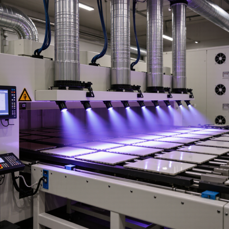
A UV curing system should start with the production problem, not the lamp catalogue. Record substrate type, coating thickness, line speed, web width, and acceptable scrap levels. The U.S. Environmental Protection Agency notes that ultraviolet-curable coatings can reach near-100% solids. That can reduce solvent emissions, but only when the formulation cures completely.
Measure the darkest ink, tallest component, and fastest conveyor setting. These details expose weak irradiance and shadowing risks. RadTech industry reports identify UV and electron-beam applications across printing, electronics, wood, and industrial coatings. Their market data also indicates continued growth in UV/EB adoption. Treat forecasts as direction, not proof. Your line may need different priorities.
Ask operators to describe real production conditions. Dust, lamp-window contamination, cooling interruptions, and uneven part spacing affect cure quality. A radiometer should verify dose at several conveyor positions, not just beside the lamp. Target dose, peak irradiance, and exposure time must match the technical data sheet. The International Organization for Standardization provides guidance for measuring UV radiation, but factory validation remains essential. A polished trial can still mislead. Test aged lamps, restart cycles, and the worst-case color. I would also leave capacity headroom; a system running at maximum output has little room for seasonal heat, maintenance delays, or a faster future line.
Map UV curing stages before choosing equipment. Start with substrate preparation, where dust, moisture, and surface energy affect adhesion. Record line speed, coating thickness, web width, and substrate temperature. Smithers’ UV LED Curing Market report identifies electronics, printing, and industrial coatings as major application areas, reflecting varied process demands. The same lamp cannot suit every station.
Place the curing stage immediately after coating or printing, then define its required dose and exposure time. A radiometer should measure irradiance across the working width, not only at the center. RadTech’s 2023 UV+EB Technology Roadmap highlights lower VOC potential, rapid processing, and improved energy control as important adoption drivers. In practice, curing quality also depends on lamp distance, shielding, ventilation, and photoinitiator response. Small changes matter.
Connect curing data with inspection and reject handling. Track dose, conveyor speed, lamp temperature, and defect location for each batch. IEC 62471 provides photobiological safety guidance for optical radiation, so guarding and interlocks belong in the line map. Build a verification point after curing, such as rub resistance, hardness, or adhesion testing. Do not assume a tack-free surface means full cure. That shortcut can fail. Line trials should include slow-speed and maximum-speed conditions, because production rarely behaves like a laboratory test.
| Stage | Production-Line Position | Primary Objective | Recommended UV Curing Approach | Typical Operating Window | Key Process Controls | Quality Verification | Integration Considerations | Risk Level |
|---|---|---|---|---|---|---|---|---|
| 1Surface Preparation | Before dispensing, coating, printing, or bonding | Remove dust, oil, moisture, and release residues so the UV material can wet and adhere consistently. | Use cleaning, plasma, corona, or controlled abrasion before the UV process. UV curing should not begin until the substrate surface is stable and dry. | Surface temperature commonly maintained between 18–30°C; relative humidity often controlled at 40–60% for sensitive bonding processes. | Surface cleanliness, contact angle, substrate temperature, humidity, and time between cleaning and coating. | Visual inspection, dyne or surface-energy testing where applicable, contact-angle testing, and adhesion checks. | Install the preparation station upstream of the dispenser and interlock the line if cleaning confirmation is unavailable. | Controlled |
| 2Material Dispensing or Coating | At the application head or coating station | Apply a consistent volume, width, thickness, or bead profile of UV-curable adhesive, ink, coating, or encapsulant. | Use metered dispensing, slot-die coating, screen printing, inkjet printing, or spray application according to the material and product geometry. | Wet-film thickness may range from approximately 10–500 µm depending on the application; bead volume is controlled by pressure, time, nozzle size, and material temperature. | Material viscosity, nozzle condition, flow rate, coating weight, wet-film thickness, and dispense start/stop timing. | Gravimetric checks, inline camera inspection, laser profile measurement, coating-weight measurement, and bead-width verification. | Provide a stable conveyor datum, synchronized motion control, and sufficient clearance for the UV head after application. | Critical |
| 3Pre-Cure or Tack Cure | Immediately after dispensing, printing, or placement | Partially solidify the material to prevent spreading, movement, sagging, or contamination before final cure. | Use a low-to-moderate irradiance UV LED station positioned close to the workpiece, with shielding to limit exposure to operators and nearby equipment. | Typical dose: approximately 50–500 mJ/cm²; typical irradiance: approximately 0.1–1.0 W/cm². Actual values depend on the formulation and required tack level. | UV wavelength, irradiance, dose, exposure time, working distance, conveyor speed, and material position after curing. | Surface tack test, dimensional inspection, positional accuracy, and visual confirmation that the material has stopped flowing. | Place the station before mechanical handling, robotic transfer, or clamping operations that could disturb uncured material. | Controlled |
| 4Component Placement or Assembly | After tack cure and before final curing | Hold components, labels, lenses, covers, or substrates in the required position while preserving access for final UV exposure. | Combine tack curing with automated pick-and-place, vision alignment, fixtures, or temporary clamps. Keep the final cure path free from shadowing where possible. | Placement tolerance commonly specified by product design; fixture contact pressure and part distortion should be minimized. | Part position, bond-line thickness, alignment, component tilt, fixture repeatability, and contamination control. | Machine-vision measurement, coordinate inspection, bond-line imaging, and sample-based pull or shear testing. | Use transparent or UV-permeable fixtures only when compatible with the wavelength and process. Avoid opaque features that block the light path. | Critical |
| 5Primary UV Cure | Main curing tunnel, flood station, focused lamp, or multi-axis UV head | Convert the applied material to its specified mechanical, chemical, and optical performance. | Use LED or arc-lamp curing selected according to the photoinitiator absorption range, product geometry, line speed, and thermal limits. | Common production dose range: approximately 500–4,000 mJ/cm²; irradiance may range from approximately 0.2–5.0 W/cm². Some formulations require multiple wavelengths or multiple passes. | Measured dose, irradiance uniformity, wavelength, lamp aging, working distance, conveyor speed, substrate temperature, and exposure count. | UV radiometer verification, hardness or tack testing, solvent-rub testing where applicable, adhesion testing, and destructive validation samples. | Synchronize the UV source with conveyor speed and recipe control. Use closed-loop monitoring where consistent dose is critical. | Critical |
| 6Shadow-Area or Secondary Cure | After the primary cure or at a dedicated multi-angle station | Cure regions hidden by components, narrow gaps, deep recesses, or complex three-dimensional geometry. | Use angled UV heads, rotating fixtures, secondary wavelengths, or a compatible thermal or moisture cure when the material system supports dual-curing. | Additional exposure commonly ranges from approximately 200–2,000 mJ/cm², depending on the depth and accessibility of the shadowed area. | Light-path coverage, part orientation, fixture rotation, shadow mapping, and confirmation of dual-cure compatibility. | Cross-section analysis, hardness mapping, fluorescence inspection where suitable, adhesion testing, and internal void or uncured-material checks. | Perform a geometry and shadow analysis during line design. Do not assume that a top-mounted UV source cures concealed surfaces. | Critical |
| 7Cooling and Thermal Stabilization | Immediately downstream of high-intensity UV exposure | Return the part and substrate to an acceptable handling temperature and reduce thermal stress. | Use forced air, heat sinks, chilled fixtures, or controlled dwell time when the UV source produces significant infrared or process heat. | Many temperature-sensitive assemblies are managed below approximately 60–80°C, while the actual limit is defined by the substrate, components, and adhesive. | Part temperature, cooling-air flow, cooling time, fixture temperature, and dimensional stability. | Infrared temperature measurement, thermocouples during validation, dimensional inspection, and post-cure warpage checks. | Separate the cooling zone from dust-generating operations and prevent airflow from disturbing uncured edges or lightweight parts. | Controlled |
| 8Inline Inspection | After curing and cooling, before packaging or final assembly | Confirm that the UV process produced the required coverage, appearance, position, and cure condition. | Integrate machine vision, UV dose logging, dimensional measurement, and selected non-destructive inspection methods. | Inspection frequency may be 100% for critical visual or dimensional characteristics, with periodic destructive testing for process validation. | Surface appearance, color, gloss, bead width, coating coverage, component position, defects, and UV dose history. | Camera-based inspection, barcode or recipe traceability, automated reject handling, and statistical process control. | Link inspection results to the UV recipe, lot number, operator, conveyor speed, and measured dose for traceability. | Verified |
| 9Final Performance Testing | Quality-control station before release | Verify that the cured product meets functional and durability requirements under intended use conditions. | Use product-specific tests such as pull strength, shear strength, abrasion resistance, solvent resistance, optical transmission, or electrical testing. | Acceptance criteria are product-specific. Testing should include validated minimum UV dose and worst-case geometry conditions. | Test method, sample size, cure history, environmental conditioning, failure mode, and measurement-system capability. | Record test results against the production lot and retain representative samples for process audits. | Use a documented reaction plan for failures, including material quarantine, dose review, lamp inspection, and revalidation. | Verified |
| 10Packaging and Traceability | End of the production line | Protect the cured product and preserve process records through shipment and later quality review. | Use packaging compatible with the product temperature, surface condition, and any remaining post-cure reaction. | Packaging conditions typically remain within the product specification for temperature, humidity, cleanliness, and allowable handling time. | Label accuracy, batch identification, cure recipe, measured dose, inspection status, and reject disposition. | Barcode or RFID tracking, electronic batch records, automatic label verification, and controlled release status. | Prevent packaging before the part has reached its handling temperature or before any required post-cure dwell is complete. | Controlled |
| 11System Monitoring and Maintenance | Across all UV curing stations | Maintain stable output, reduce unplanned downtime, and ensure that the delivered UV dose remains within the validated process window. | Use radiometer checks, lamp or LED status monitoring, cooling-system alarms, shutter controls, recipe management, and preventive maintenance. | Verify UV output at defined intervals, commonly at start-up, after maintenance, and according to the validated production schedule. | UV output trend, irradiance uniformity, cooling performance, lamp hours, LED temperature, conveyor speed, and alarm history. | Calibrated radiometer, maintenance log, alarm history, spare-part plan, and documented change-control procedure. | Install safety interlocks, shielding, emergency stops, access-door switches, ozone extraction where applicable, and operator exposure controls. | Critical |
Process note: The UV dose and irradiance values shown are common engineering ranges for production planning, not universal specifications. Final settings must be validated with the selected formulation, substrate, part geometry, wavelength, conveyor speed, working distance, and product-performance requirements. UV systems should be installed with appropriate shielding, interlocks, ventilation, and worker-exposure controls.
Integrating UV curing into a production line starts with matching the lamp to the chemistry. UV LED systems often provide stable output at selected wavelengths, such as 365, 385, or 405 nanometers. Mercury-based lamps can deliver broader spectral energy, which may suit coatings with multiple photoinitiators. The correct choice depends on absorption depth, coating thickness, line speed, and heat sensitivity. Do not select a lamp by wattage alone. Measure irradiance at the actual curing position.
Wavelength matters greatly. A surface may feel dry while deeper layers remain soft. This can cause poor adhesion, cracking, or later yellowing. Use a calibrated radiometer to check irradiance and calculate dose during commissioning. Keep the lamp-to-product distance consistent. Small height changes can alter curing results. I have found that conveyor speed is often adjusted too quickly when curing fails. Changing the wavelength or exposure geometry may solve the problem better.
Tips: Use closed-loop controls when possible. Monitor lamp temperature, conveyor speed, irradiance, and product presence. Add shielding, interlocks, and suitable ventilation, especially when the process can generate heat or ozone. Record readings each shift, not only during installation. Test samples after cooling, because immediate inspection can be misleading. A useful control plan includes alarm limits and scheduled lamp maintenance. Still, real production varies. Dust, uneven surfaces, and aging components can defeat a carefully designed setup. Review the data before making another adjustment.
Integrating a UV curing system begins with the production line, not the lamp housing. Map conveyor speed, product spacing, cure distance, and available electrical capacity. Leave service access around the chamber. Technicians should confirm guarding, emergency stops, shielding, and ventilation before energizing equipment. These controls protect operators from optical and mechanical hazards. They also support a repeatable installation record. In practice, our first timing estimate is often wrong. Product geometry changes the required exposure.
Mount the curing head squarely over the target surface, then align it with a test fixture. Use a calibrated radiometer to measure intensity at the actual working distance. Connect system signals to the line controller, including run, ready, fault, and cure-permit status. The conveyor should not release uncured parts downstream. Add interlocks for access doors, cooling flow, and over-temperature conditions. Keep cable routes separate from high-noise power circuits. Small wiring mistakes can create large delays.
Synchronize exposure with motion, rather than treating curing as a separate operation. Encoder feedback can adjust triggering when line speed changes. Trial several speeds and record dose, surface tack, adhesion, and temperature. Inspect parts after cooling, not only directly beneath the source. A short production run reveals gaps that bench tests miss. We once overlooked a reflective fixture edge. It altered the dose pattern. Review results with operators, document settings, and schedule periodic intensity checks. Leave room to improve.
This chart shows the calculated UV exposure time for a 1-meter curing zone. As conveyor speed increases, exposure time decreases, so lamp output and line synchronization must be adjusted to maintain the required curing dose.
Calculation: exposure time = curing-zone length ÷ conveyor speed. Values are based on a 1-meter UV curing zone and line speeds commonly used for continuous production equipment.
Integrating a UV curing system is not complete when the first parts look dry. Cure quality needs measurable evidence. During production trials, record UV dose, irradiance, conveyor speed, lamp distance, and material batch. Test both the surface and the cure depth. A tack-free finish can still hide weak adhesion underneath. Use adhesion checks, solvent resistance tests, and cross-sections where practical. Repeat these checks after setup changes. Small shifts matter.
Safety validation should cover the whole cell, not only the lamp housing. Confirm shielding, door interlocks, emergency stops, warning indicators, and restricted access. Measure stray UV around access points during commissioning. Check ventilation when the process may generate ozone or vapors. Operators need clear procedures, suitable protective equipment, and documented training. Keep records. Do not rely on assumptions.
Ongoing performance depends on trends, not occasional inspection. Set a baseline for dose and irradiance, then review readings at defined intervals. Track rejected parts, lamp hours, temperature, and conveyor speed. A sudden dose drop may indicate contamination, aging emitters, or a sensor problem. Planned cleaning and calibrated instruments improve confidence. Our early checks were too optimistic; visual inspection missed under-cured areas. That mistake changed the process. Revalidate when coatings, line speed, or component geometry changes. Reliable curing requires evidence and the willingness to question a result that looks perfect.
Map substrate preparation, coating, curing, inspection, and reject handling. Record dust, moisture, surface energy, line speed, coating thickness, web width, and substrate temperature. Small changes matter.
Place it immediately after coating or printing. Define the required UV dose and exposure time at that exact position. The line is not a laboratory.
Use a calibrated radiometer across the full working width. Center-only readings can hide weak areas near the edges. Measure at the product surface.
Match the lamp spectrum to the coating chemistry and photoinitiator response. Selected UV wavelengths suit some systems, while broader output suits others. Wattage alone is insufficient.
Surface drying does not prove complete curing. Deeper layers may stay soft, causing weak adhesion, cracking, or later color changes. That shortcut can fail.
Track dose, irradiance, conveyor speed, lamp temperature, product presence, and defect location. Record readings each shift, not only during installation.
Use shielding, guarding, interlocks, and suitable ventilation. Heat and optical radiation require careful control. Safety planning should be built into the line map.
Test rub resistance, hardness, or adhesion after curing. Inspect samples after cooling because immediate results can mislead. A clean surface can still fail later.
Test both slow and maximum speeds. Production rarely behaves like a laboratory trial. If curing fails, changing geometry or wavelength may help more than slowing the conveyor.
Set alarm limits, inspect lamp condition, and review irradiance trends. Dust, uneven surfaces, and aging components can defeat a careful setup. The plan may still need revision.
Learning how to integrate uv curing systems into production lines begins with clearly defining production needs, including material types, coating or adhesive requirements, line speed, curing area, and available space. Once these factors are understood, manufacturers can map each UV curing stage across the workflow to determine where curing, inspection, cooling, or additional processing should occur. This approach helps create a practical system layout while reducing bottlenecks and unnecessary energy use.
The next steps involve selecting suitable UV lamps, wavelengths, power levels, and control methods for consistent curing. The system should then be installed and synchronized with conveyor speed, sensors, material handling equipment, and production controls. Before full operation, teams should validate cure quality through performance testing and confirm that shielding, ventilation, interlocks, and operating procedures support a safe workplace. Regular monitoring, maintenance, and process reviews will help sustain curing performance, product quality, and production efficiency over time.

LumiCure Light